Squirt 2
Squirt 2 - Advanced Turbine Jet-Boat Project.
Jump to:
Squirt 2 will be our second turbine jet boat. We will be using a surplus US Air Force helicopter turbine and speed decreaser gear-box (SDG) and a specially designed billet jet pump.
"Cuz' - It's Fun To Do Bad Things! "
This is the T58-GE-8F turbine that is going in Squirt 2. It weighs 350 lbs and produces 1,370 hp @ 6000 rpm. That's about 1,200lbs-ft of torque! The hull shown in the photos below is a 21ft aluminum white water race boat built by Eagle Power Boats. We have ordered a 23ft step V version of this boat for our project.


Some shots from my trip to Eagle. We tried the turbine mock-up in a couple different boats they had in production.


Shots of Squirt 2 at the factory - Notice the stepped hull design inside. The stringers were built extra strong to take the torque of the turbine.


Dissecting the American Turbine SD-309 bowl. We were going to modify this bowl for reverse rotation, but now I am planning to build a new billet bowl from scratch. The output shaft on the T58 turns the wrong way for a normal Jet Pump.


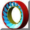
Here are some preliminary screen shots of the NT billet pump bowl with a replaceable stator insert. This bowl will allow us to turn a special reverse rotation impeller. The welded steel stator is designed to be removed and re-installed quickly, this will allow us to try different stators for pump tuning. The number of vanes, entry angle exit angle are the three primary stator variables.

This is my progress so-far with the Jet Drive. We expect to turn this from billet 6061-T6 on a CNC Lathe. The design has been improved immensely from the first prototype. We have abandoned the idea of using the original bowl that we cut apart.
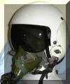
This is the type of helmet I expect we will need to communicate while driving Squirt 2.
![]()
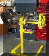
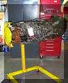
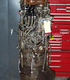
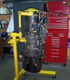
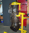
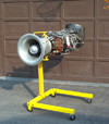
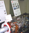
Some shots of the engine. We need to modify the power turbine to allow it to work in the exhaust up position. Normally this engine is installed in pairs with one exhaust left and one right. We are building all the fixtures needed to turn the housing properly.
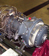
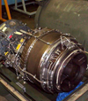
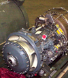
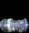
T53-L13B Turbine Engine.(The engine we did not use)
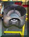

Power turbine (left) and intake (right). I intend to mount an alternator on the fuel purifier drive pad in the upper right side of the accessory gear box.
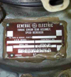
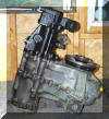
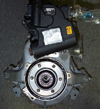
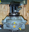
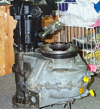
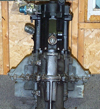
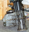
3.25:1 Torque sensing speed reducer. The input is in the lower left, output on the right, The black part in the upper left is the lube oil pump. Max input speed is 20,000 rpm. We will make a 4340 billet adapter flange for the output spline. The brake caliper will be mounted right on the back of the gearbox.
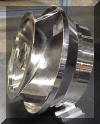
This is what the billet CNC machined, nickel plated steel impeller from PJD will look like.

Check out this trick 3 piece billet bowl designed by Rob Chrunyk at Eagle Power Boats! This is the bowl we will use in Squirt 2. Now that Rob has made this bowl available, there is no need for us to continue developing the NT billet bowl design (unless you want to try one. If so contact


American Turbine Trim Nozzle and Angle Piece.

Here is a good shot of the Eagle Bowl.

This view shows the special tool we made for pulling the rear half of the inner race of bearing #5. We had to fabricate several tools like this to use on various parts of the power turbine assy. This is definitely not a do it yourself at home project.
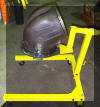


This is the jig I made for relocating the power turbine accessory drive pad. The jig accurately aligns the pad and holds it securely during welding. The entire casing is made of Hastalloy-X and requires special welding procedures. Zyglo inspection after welding confirmed a crack-free job.
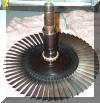
This is the power turbine wheel itself. It's hard to believe you can get 1,400hp @ 20,000rpm out of this little (14") wheel. The #4 bearing (roller) is still on the shaft the forward half of the #5 bearing inner race is there too.
![]()

This is my brother Steve Nye's slick idea for stacking the power turbine assembly. The press-fit is tricky considering the bearing must be heated and the alignment must be maintained for correct balance. We machined a mandrel for each end of the power turbine shaft and used the tail stock of a lathe to press the bearing on horizontally.
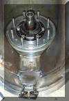
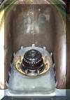
These views show the tail end of the power turbine shaft. The constant velocity high speed coupling employs several balls, is slip fit over the polygon coupling and is retained by a special nut and key washer. Needless to say proper stack up tolerances and assembly torque are critical here. The view on the right shows the power turbine housing complete with high speed coupling and forward section of the heat shield ready for mating with the SDG (speed decreaser gear). The SDG seals against the bearing housing with an "O"-ring, no gasket is used here.
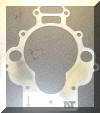
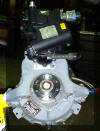
This is the special SDG oil pump programming plate I designed in AutoCAD 2000 and had water jet cut by my friends at The Waterjet Workshop in Mississauga.

The beefy output flange and caliper bracket.
The 1/2" aluminum caliper bracket was also cut by The Waterjet Workshop.


Brake caliper and disk with integral pulley. I decided to drive the alternator with a V-belt off the output shaft instead of the fuel purifier pad on the engine.
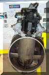
Yours Truly stacking the SDG to the Power Turbine. (This was quite tricky as the studs are almost totally inaccessible).


This is how we verified the SDG oiling system modifications. The 4 L container hanging on the crane holds the $10.00 / L turbine oil. We have made several modifications to the lube system to allow upright operation and I want to make sure that everything is alright. The drive shaft U joints are wrapped in masking tape to keep them from flopping around during the spool up test.

I used a 1/2" shop air line with a big nozzle to spool-up the power turbine, SDG and oil pump.

Steve and I celebrate a flawless run-up at the end of the day with a few cold bottles of Molson's Canadian. We are both feeling very confident at this point!
I AM CANADIAN!

Here is the fully assembled engine (hanging by a strap to the power turbine) ready to test fit in Squirt 2. The silver cylinder on the front of the engine contains the starter. This is also a good view of the billet jet pump.

Close up of the SDG and exhaust. The drive shaft is still wrapped in tape at this point.

I have yet to fabricate the engine mounts and an intake screen.


This is how it ia progressing.

View from under the bow. (seats removed) Notice how the compressor is sealed. I will never run the engine without a proper intake screen fitted.
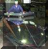
Here is what Squirt 2 looks like after hours of polishing. It still needs a final buffing, but it looks awesome!


These are the plates and the finished Instrument panels. The switch with the red safety cover is for the afterburner system. The switch in the hatched yellow area is for the N2 brake or "line-lock".


I decided to go with a polished aluminum checker-plate deck. It vibrates and makes a lot of noise, but it is strong and easy to mount stuff to. The master cylinder for the rotor brake is visible in the left photo.
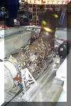
The square aluminum valve block on the port side in-front of the oil tank is the afterburner streak and main fuel control.
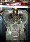
The two black tanks are for oil. Port side tank is for turbine lube. Starboard side is for SDG.
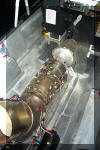
The braded lines leading from the oil tanks to the PT housing are vents.


The intake screen turned out well. Notice the "NT" water jet cut into the front motor mounts.


Here are some good shots of the engine mounted in Squirt 2 at the Toronto Boat Show.


Toronto Boat Show.
Squirt 2 was in the Performance Boat Club of Canada Booth.


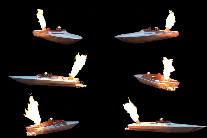
The after-burner in action in-front of the National Trade Center. (Toronto Boat Show) The after-burner is for show only and has nothing to do with the operation of the engine.
![]()
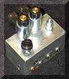
This is a close-up of our custom after burner control valve. It has two solenoids, one for streak (to light the fire) and one for fire. The two adjustments are: Bias (we are stealing fuel from the main fuel control) and Output (fire size). This unit was designed to work on the T58, but will work on other engines too.
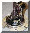
This is the accessory drive shaft. All starting and accessory drive loads are transmitted by this little shaft. The starter motor has a torque limiting slip clutch that normally prevents accessory shaft breakage. If you have a Lear starter you should be OK, but if you have an older GE starter beware that the slip clutch is probably rusty and seized solid. If you try to start with a seized slip clutch, you risk breaking this shaft. To solve this problem I developed the NT "soft start" solenoid, it works!
![]()
The SDG oil cooler has seven 1/2" aluminum water tubes. Water is tapped off the jet pump. Oil temp never exceeds 85 deg C.
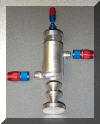

The fuel deaerator is designed to remove air bubbles from the fuel. The engine would tend to loose power and flame-out in rough water before I built this device.

Here is a good shot of Squirt 2 on her maiden voyage.
![]()
![]()
![]()
Squirt 2 puts up a wall of water during a turn with the power on.
![]()
Here is a shot of Squirt 2 at speed.
![]()
Smoke and fire show for the crowd. (engine is at idle)

Docking the beast! A jet drive with a brake is very easy to maneuver.
~~~~~~~~~~~~~~~~~~~~~~~~~~~~~~~~~~~~~~~~~~~~~~~~~~~~~~~~~~~~
Squirt 2 Streaming Videos
Note:
Please wait while the videos download from our server.
lr_small.jpg) |
 |
lr_small.jpg) |
 |
 |
 |
 |
 |
lr_small.jpg) |
 |
 |
 |
 |
 |
 |
~~~~~~~~~~~~~~~~~~~~~~~~~~~~~~~~~~~~~~~~~~~~~~~~~~~~~~~~~~~~


